ArgoBot Drive Training
Here you'll find some tutorials to write drive code for the ArgoBot (or any robot) using LabVIEW or C++
This project is maintained by FRC1756-Argos
Tutorial 8: Speed Ramping
Debounce is a great way to prevent unwanted input change in digital inputs, but what about joysticks and other analog inputs? If we want to control how quickly an analog input can change values, we can use an approach called speed ramping.
What is “speed ramping”
Analog inputs, unlike digital inputs, can have a range of values. Sometimes analog inputs change rapidly, but these rapidly changing values aren’t as useful as more steady values. For example, if you go from full forward to full reverse on the robot very quickly, the quick change in direction can stretch chain and put additional wear on drivetrain components.
Consider the following:
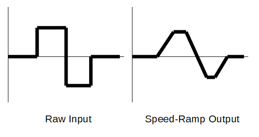
Notice how the raw input has a fast change from positive to negative, but the output smoothly transitions. This linear ramping is a simple way to prevent “jerkiness” on the output.
Control Design
To perform this ramping, we will utilize similar concepts to debounce where the program will compare the desired output to the previous output and ensure the difference between the previous output and the new output is below some threshold value. This is effectively finding the slope the line in the diagram above and enforcing a maximum slope.
C++
Conceptual Overview
This will be similar to debounce, but now we’ll use time to control our ramp speed. We’re also going to need to maintain state for each ramping instance. To do this, we will be making an object like in debounce. We’ll get started and go through each of these concepts along the way.
Create A Speed Ramp Class
- In other tutorials, we made functions to implement our design. This time we’re going to make a class. We’ve actually made a class before when we made DriveSubsystem, but this time we’ll go through some of the components in detail.
- Open
DriveSubsystem.hand add a class declaration forSpeedRampin theprivatesection:class SpeedRamp { public: private: }; - In this new class, we need to add the member variables that keep track of the state we need to implement ramping.
class SpeedRamp { public: private: const double m_pctPerSecond; double m_lastOutput; std::chrono::time_point<std::chrono::steady_clock> m_lastUpdateTime; };-
m_pctPerSecondis how fast our ramping allows values to change in percent per second. -
m_lastOutputis the previous output value. We’ll use this to ensure values don’t change too quickly. -
m_lastUpdateTimeis the time we last updated the output. We’ll use this to calculate the maximum change between samples
-
- Now that we have member variables, we will declare a constructor. This is where we initialize the member variables.
 class SpeedRamp {
   public:
     SpeedRamp(double pctPerSecond);
   private:
     const double m_pctPerSecond;
     double       m_lastOutput;
     std::chrono::time_point<std::chrono::steady_clock> m_lastUpdateTime;
 };
Our constructor takes one parameter
pctPerSecondsince the other two values are only used internally. - The last missing piece is a function to generate ramped outputs
class SpeedRamp { public: SpeedRamp(double pctPerSecond); double operator()(const double newSample); private: const double m_pctPerSecond; double m_lastOutput; std::chrono::time_point<std::chrono::steady_clock> m_lastUpdateTime; };operator()is a special function that lets us use parentheses like our class instance (an object) can be called like a function. We’ll see this in action soon.std::chrono::time_point<std::chrono::steady_clock>is part of the C++ time library that lets us calculate elapsed times easily. - We should also add the
chronolibrary to our include list at the top ofDriveSubsystem.h#include <chrono> - Now that we have our class declared, we’ll add the implementation to
DriveSubsystem.cpp - Let’s start with defining our constructor.
 DriveSubsystem::SpeedRamp::SpeedRamp(double pctPerSecond)
   : m_pctPerSecond{pctPerSecond}
   , m_lastOutput{0}
   , m_lastUpdateTime{std::chrono::steady_clock::now()} {}
This is very similar to other constructors. The one new piece is how we initialize m_lastUpdateTime.
std::chrono::steady_clock::now()reads the current time so we can do time differences later. - Next, let’s work on our
operator()definitiondouble DriveSubsystem::SpeedRamp::operator()(const double newSample) { } - First, we’ll want to know the current time so we can compare it to the previous sample time and ramp our output
double DriveSubsystem::SpeedRamp::operator()(const double newSample) { auto now = std::chrono::steady_clock::now(); } - Having the current time is great, but what we really want is the time since our last update.
double DriveSubsystem::SpeedRamp::operator()(const double newSample) {
  auto now = std::chrono::steady_clock::now();
  auto milliseconds = std::chrono::duration_cast<std::chrono::milliseconds>((now - m_lastUpdateTime)).count();
  auto seconds = milliseconds / 1000.0;
}
This is a little complicated, but let’s break it down.
-
(now - m_lastUpdateTime)calculates the elapsed time since last update -
std::chrono::duration_cast<std::chrono::miliseconds>()converts this elapsed time to milliseconds since we want fractional seconds in the end and manystd::chronofunctions use integer values. -
.count()returns the number of milliseconds -
milliseconds / 1000.0converts the integer milliseconds to a decimal seconds value
-
- Next, we need to know whether the ramp should increase or decrease output values.
double DriveSubsystem::SpeedRamp::operator()(const double newSample) { auto now = std::chrono::steady_clock::now(); auto milliseconds = std::chrono::duration_cast<std::chrono::milliseconds>((now - m_lastUpdateTime)).count(); auto seconds = milliseconds / 1000.0; auto changeDirection = std::copysign(1.0, newSample - m_lastOutput); }std::copysignis used to copy the sign (positive or negative) from the second parameter (newSample - m_lastOutput) to the first parameter (1.0). In this case,changeDirectionwill be either+1.0or-1.0. - Now we’ll calculate the magnitude of change the user has requested
double DriveSubsystem::SpeedRamp::operator()(const double newSample) { auto now = std::chrono::steady_clock::now(); auto milliseconds = std::chrono::duration_cast<std::chrono::milliseconds>((now - m_lastUpdateTime)).count(); auto seconds = milliseconds / 1000.0; auto changeDirection = std::copysign(1.0, newSample - m_lastOutput); auto desiredChangeMagnitude = std::abs(newSample - m_lastOutput); } - However, we also need to know how much change the speed ramping allows given the time elapsed since the last update
double DriveSubsystem::SpeedRamp::operator()(const double newSample) { auto now = std::chrono::steady_clock::now(); auto milliseconds = std::chrono::duration_cast<std::chrono::milliseconds>((now - m_lastUpdateTime)).count(); auto seconds = milliseconds / 1000.0; auto changeDirection = std::copysign(1.0, newSample - m_lastOutput); auto desiredChangeMagnitude = std::abs(newSample - m_lastOutput); auto maxTimeRampMagnitude = m_pctPerSecond * seconds; } - And let’s put this information together to determine the allowed change
double DriveSubsystem::SpeedRamp::operator()(const double newSample) { auto now = std::chrono::steady_clock::now(); auto milliseconds = std::chrono::duration_cast<std::chrono::milliseconds>((now - m_lastUpdateTime)).count(); auto seconds = milliseconds / 1000.0; auto changeDirection = std::copysign(1.0, newSample - m_lastOutput); auto desiredChangeMagnitude = std::abs(newSample - m_lastOutput); auto maxTimeRampMagnitude = m_pctPerSecond * seconds; auto delta = changeDirection * std::min(desiredChangeMagnitude, maxTimeRampMagnitude); }std::minis a function that returns the smallest value from a list of parameters. - Great! Almost done. Finally, we’ll generate our output
double DriveSubsystem::SpeedRamp::operator()(const double newSample) {
  auto now = std::chrono::steady_clock::now();
  auto milliseconds = std::chrono::duration_cast<std::chrono::milliseconds>((now - m_lastUpdateTime)).count();
  auto seconds = milliseconds / 1000.0;

  auto changeDirection = std::copysign(1.0, newSample - m_lastOutput);
  auto desiredChangeMagnitude = std::abs(newSample - m_lastOutput);
  auto maxTimeRampMagnitude = m_pctPerSecond * seconds;
  auto delta = changeDirection * std::min(desiredChangeMagnitude, maxTimeRampMagnitude);

  m_lastOutput += delta;
  return m_lastOutput;
}
Notice that we’re using the
+=operator. This is equivalent to sayingm_lastOutput = m_lastOutput + delta. We have to make sure we update the stored value so we can use it in the future.
You just made a new class! Congratulations! Next, we’ll add this to Arcade Drive and try it out.
Add Speed Ramp To The Drive Function
- We need to add objects of this new class type to one of our drive functions to try it out.
- Start with the
ArcadeDrive()function we have inDriveSubsystem.cppvoid DriveSubsystem::ArcadeDrive(const double forwardSpeed, const double turnSpeed) { m_leftDrive.Set(ControlMode::PercentOutput, forwardSpeed + turnSpeed); m_rightDrive.Set(ControlMode::PercentOutput, forwardSpeed - turnSpeed); } - Next, we’ll add two ramp objects for our two joystick inputs
void DriveSubsystem::ArcadeDrive(const double forwardSpeed, const double turnSpeed) { static auto forwardRamp = SpeedRamp(0.5); static auto turnRamp = SpeedRamp(0.5); m_leftDrive.Set(ControlMode::PercentOutput, forwardSpeed + turnSpeed); m_rightDrive.Set(ControlMode::PercentOutput, forwardSpeed - turnSpeed); }staticindicates that we want to re-use these objects across calls to this function. If we left this out, the ramp parameters would be reset continuously and we’d always get 0 output. - Finally, we need to use these ramp objects to replace the raw joystick inputs
 void DriveSubsystem::ArcadeDrive(const double forwardSpeed, const double turnSpeed) {
   static auto forwardRamp = SpeedRamp(0.5);
   static auto turnRamp = SpeedRamp(0.5);
   const auto rampedForwardSpeed = forwardRamp(forwardSpeed);
   const auto rampedTurnSpeed = turnRamp(turnSpeed);
   m_leftDrive.Set(ControlMode::PercentOutput, rampedForwardSpeed + rampedTurnSpeed);
   m_rightDrive.Set(ControlMode::PercentOutput, rampedForwardSpeed - rampedTurnSpeed);
 }
Notice how we can do
forwardRamp(forwardSpeed)to use our ramp objects? This is how we useoperator().
That’s it! you now have a speed ramp added to your Arcade Drive function.
Try It Out
- Before you deploy your code, make sure Arcade Drive is set as the default command for your drive subsystem in the
RobotContainerconstructor. - Deploy your code.
- Try driving around
LabVIEW
Implement the Design
- Start by making a new VI named
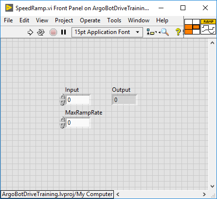
SpeedRamp.viwith two numeric inputs and one numeric output - At this point your front panel should look like the following:
- Switch to the block diagram
- In addition to the feedback node we used to make debounce, we’re going to use the
In Range and CoerceVI. This VI both detects if an input is between two values and generates an output value that is guaranteed to be between two values. For example, if we provide an expected range of 0 to 1 with an input of 1.2, theIn Range and CoerceVI would outputfalsebecause 1.2 is greater than 1 and the coerced output would be1. You can find theIn Range and CoerceVI here: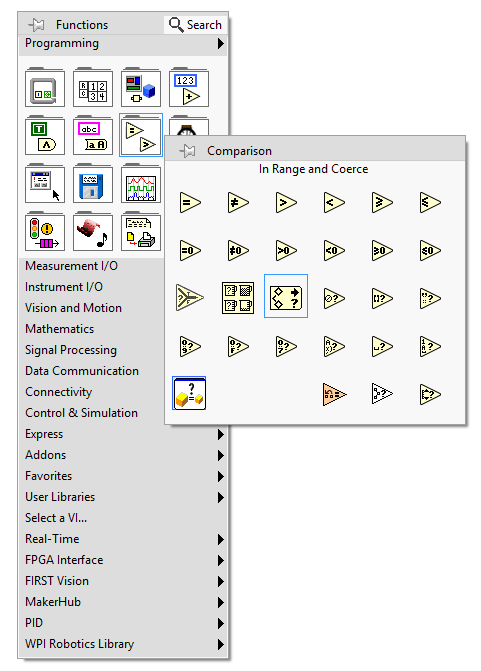
- Now, we want to implement the following pseudocode
variables: MaxRampRate, CommandedChange, In, PrevOut, Out

if firstRun:
    PrevOut = In
    SampleCount = 0

CommandedChange = In - PrevOut

if CommandedChange > MaxRampRate:
    CommandedChange = MaxRampRate
else if CommandedChange < -MaxRampRate:
    CommandedChange = -MaxRampRate

Out = PrevOut + CommandedChange

PrevOut = Out

Loop
- If you have an idea how to do this, go ahead and try it now before viewing the solution.
- I’m serious, it may seem complicated, but you’ve done all the building blocks in previous exercises
- Need some hints?
- The
if firstRunblock is known as ‘initialization’ and is necessary to set the values of the feedback nodes at the beginning. The input at the bottom of the feedback node is for initialization - The
PrevOutvariable in the pseudocode corresponds to a feedback node in the solution - The
if ... else ifblock in the middle can be represented by aIn Range and CoerceVI
- The
- OK. Now that you’ve come up with a solution on your own, see how it compares to this solution:
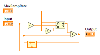
- Save your VI
Great! Now that you’re getting more comfortable in LabVIEW, you should be able to translate concepts into code more easily. Don’t worry if you had to look at the solution, but if you try it on your own first the solution may help you learn more. Now let’s use your new code
Integrate Your Code
- Open
Drive_Arcade.viand go to the block diagram - Add your speed ramp block to both of the joystick inputs like this:
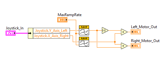
- Add a control for the ‘MaxRampRate’ input
- Insert
Drive_Arcade.viintoArgoBot_Main.vi - Run your code
- Try driving with the sample count set low (e.g. 0.01)
- Try driving with a high sample count (e.g. >0.1)
- Try rapidly moving the joysticks back and forth and see what happens
Another Bug
![]()
![]()
![]()
![]()
![]()
![]()
![]()
![]()
You just uncovered one of the tricky parts of making VIs in LabVIEW. It turns out that feedback nodes from different copies of the same VI can share values and interfere with each other. We didn’t see this when we made debounce because we only had one debounce block in our program.
Thankfully, this is easy to fix. We’ll have to change the properties of SpeedRamp.vi.
- Open
SpeedRamp.viagain - From the File menu, select VI Properties
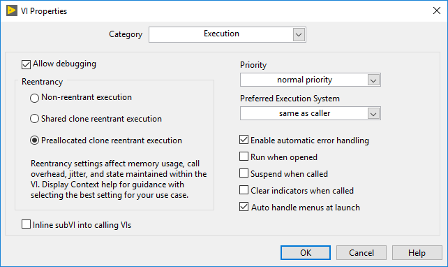
- In the VI Properties window, choose “Execution” from the Category selector
- Change Reentrancy to “Preallocated clone reentrant execution”.
- We generally use “Non-reentrant execution” for VIs that do not have state (state is kept with blocks like the feedback node)
- “Preallocated clone reentrant execution” is useful for VIs that keep state
- We typically do not use “Shared clone reentrant execution”
- The remaining settings on the Execution page should only be changed in special circumstances as they can impact code performance
- When you’re done, the Execution settings should look like this:
- Try driving again with various ramp rates
What did you notice when using the speed ramped output? Was there a noticeable difference between low and high max ramp rates?
Congratulations! You’re getting the hang of using history to enhance drive code! Next, we’ll be using what we’ve learned so far to make a turbo button!
| <-Previous | Index | Next-> |