ArgoBot Drive Training
Here you'll find some tutorials to write drive code for the ArgoBot (or any robot) using LabVIEW or C++
This project is maintained by FRC1756-Argos
Tutorial 5: Deadbands
Now that we’ve got some base drive code, let’s explore some refinements that will make it even better! First up, we’ll fix a common problem with joystick inputs.
If you don’t remember how to do any of the steps, you can go back to the previous tutorials for more explanation.
What is a “Deadband”?
You may have noticed when driving the robot, that the motors move slightly even when you don’t touch the joysticks. If you didn’t notice this, try this to see the issue:
C++
- Open
DriveSubsystem.cpp - We want to see what the joystick inputs are, so we’ll add some print statements.
- In your current drive control function, add print statements like this:
wpi::outs() << "Left speed:" << leftSpeed << ", Right speed:" << rightSpeed << '\n';The important parts of this are:
wpi::outs()outputs to the roboRIO console- The
<<are used between each printed element so variables can be formatted into a logged string \nprints a new line after each log
- Deploy the robot code.
- Enable the robot in the driver station
- While the robot is enabled, open console by clicking the gear then “View Console” in the driver station.

- A window will pop up with many log statements updating with joystick values.
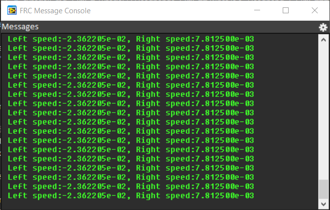
- You should see that the joystick input values rarely go back to
0.00.
LabVIEW
- Run your robot code as normal from
ArgoBot_Main.vi - Pick up the robot and hold it near your ear so you can hear the sound of the motors and motor controller
- Make sure you keep the robot wheels away from any hair, jewelry, or loose clothing. These could get tangled up in the wheels.
- Drive the robot slowly forward so the wheels just barely move
- You should hear a high-pitched sound even before the motors begin to move
- This is the sound of the motor controllers and it indicates an output, but that input is not high enough to move the robot
- Let go of the joystick, and you may still hear the sound
- Even if you don’t hear the sound, we can use the “probe” feature in LabVIEW to see the output of our drive code.
- While the code is running, open up the block diagram of
ArgoBot_Main.vi - Click on the wire going to the left motor output. This will create a probe, which is a live view of what the code is doing
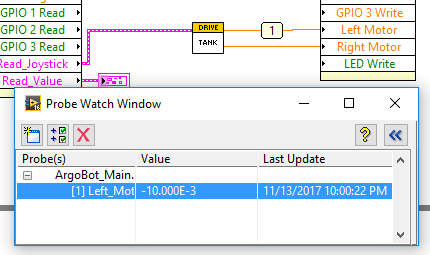
- Try moving the joystick back and forth to see the value change. Does it always go back to 0 when you let go of the joystick?
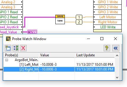
- You can monitor multiple probes at the same time! Try probing the other motor output.
- Now that we see the symptom, let’s find the cause. Open up the drive VI you’re using and probe the Joystick values
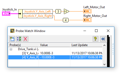
Looks like those joysticks don’t always stay at 0. This isn’t really noticeable on the ArgoBot since it needs quite a bit of output before the motors move, but on an FRC robot, 10% can be significant.
To fix this, we need a “Deadband” to designate a range of small input values that should produce no output.
Control Design
Consider the following plot:
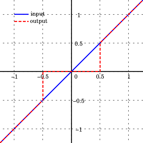
Plot by Krishnavedala (Own work) CC BY-SA 4.0, via Wikimedia Commons
For our deadband implementation, we also want to force the joystick output to 0 for small joystick input values. However, if we used the value 0.5 as shown, only half of the speed range would be available. Instead, we’ll use a threshold of 0.1 or 10%.
If you have any ideas on how to do this, try it on your own before following the step-by-step instructions.
C++
Make a Deadband Function
- Let’s start by opening
RobotContainer.hand make a new deadband function declaration. - This function should have two
doubleinput and return adoublestatic double deadband(const double input, const double threshold); - Now, in
RobotContainer.cppadd the deadband function definition.double RobotContainer::deadband(const double input, const double threshold) { } - Next, we’ll add code that implements the code design. If the input exceeds our deadband threshold, we should output the input value. Otherwise, we are in the deadband region and we’ll output 0. Keep in mind, the threshold check applies to positive and negative values, so we’ll use
std::abs()to calculate the absolute value.double RobotContainer::deadband(const double input, const double threshold) { if(std::abs(input) > std::abs(threshold)) { return input; } return 0; } - Finally, let’s add this deadband function to the calls to our drive function. We’ll use a threshold of 0.1 here, but if you can use a bigger or smaller value based on the values you saw in the console earlier.
  m_drive.TankDrive(deadband(m_controller.GetRawAxis(static_cast<int>(frc::XboxController::Axis::kLeftY)) * -1, 0.2),
                 deadband(m_controller.GetRawAxis(static_cast<int>(frc::XboxController::Axis::kRightY)) * -1, 0.2));
Try It Out
- Now that we’ve added the deadband, try deploying your code and driving the robot again.
- Check out the console output to see if it’s working as expected.
LabVIEW
Making a New VI
Sometimes, we have some code that we want to re-use in several places. In these situations we could copy and paste that code for each instance, but then making changes becomes difficult.
Instead, we’re going to make a new VI that implements our deadband.
- In the project explorer, click “File”>”New VI”. This will bring up a new front panel and block diagram.
- Save the new VI as
Deadband.vi - Right click on the I/O pattern in the top right corner of the front panel window and select a pattern with at least one box on the left and at least one box on the right.
- Inputs and outputs may go on either side of the pattern, but keeping inputs on the left and outputs on the right makes cleaner VI wiring.
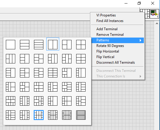
- Inputs and outputs may go on either side of the pattern, but keeping inputs on the left and outputs on the right makes cleaner VI wiring.
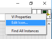
- Next, we’ll make an icon for the VI. This determines how the VI will look inside other VIs. Right click on the current icon and select “Edit Icon…”
- Use the “Filled Rectangle” tool and drag a rectangle around the window to clear the icon
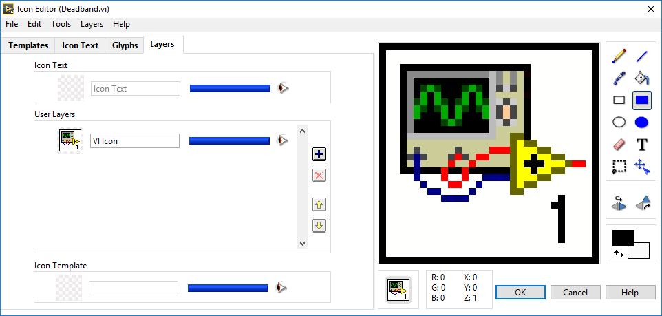
- You can change colors, add shapes, and write text to make an icon you like. Use the preview to determine if your icon is recognizable in small format.
- When writing text, use capital letters for best visibility. To move text, use the arrow keys immediately after typing.
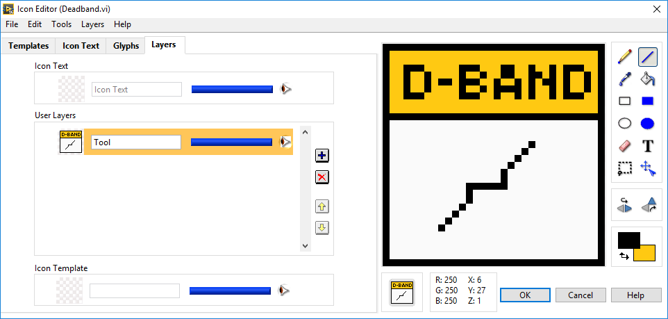
- When writing text, use capital letters for best visibility. To move text, use the arrow keys immediately after typing.
- Click “OK” when you are happy with your new icon
- Next, add a numeric control and numeric indicator to the block diagram using the controls palette on the front panel. This is accessible by right clicking in the empty space just like the tools palette in the block diagram.
- The control will be our input, and the indicator will be our output
- Name the control “In” and the indicator “Out”
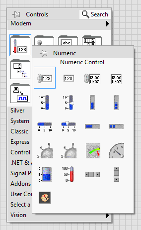
- Currently, our VI has no inputs and outputs, but we can wire our control and indicator so they become accessible outside our VI.
- Do this by first left clicking one of the left rectangles in the IO Pattern you chose. It will turn black as shown and you will get a wire cursor.
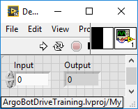
- Then click the control. The block you wired will turn orange indicating a floating point control was connected.
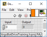
- Do the same with the output indicator.
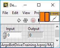
Now we have a starting point for our VI with the necessary input and output.
Add Deadband Logic
- Go to the block diagram of your new deadband VI
- Use the absolute value block from the numeric palette and the greater than and selector blocks from the comparison palette to implement the following:
if |Input| > 0.1: Output = Input else: Output = 0 - You should end up with something that looks like this:
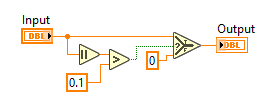
- Save your VI
Try It Out
Now, let’s add the deadband VI to our tank drive VI to see it in action.
- Open
Drive_Tank.viand go to the block diagram - Add in two instances of your deadband VI using “Select a VI…” in the tools palette
- Insert the deadbands in the joystick inputs as shown here:

- Add
Drive_Tank.vias the drive block inArgoBot_Main.vi - Run
ArgoBot_Main.vi - Probe before and after the deadband blocks
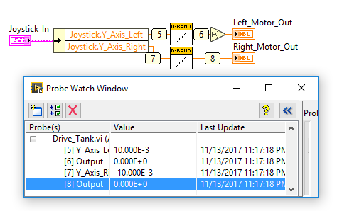
How does this work compared to the non-deadbanded tank drive?
Congratulations! You just made your first VI from scratch! Creating new VIs is an easy way to reuse and organize code.
You can add this deadband to any drive VI, but we’re going to try another approach for our next exercise.
| <-Previous | Index | Next-> |