ArgoBot Drive Training
Here you'll find some tutorials to write drive code for the ArgoBot (or any robot) using LabVIEW or C++
This project is maintained by FRC1756-Argos
Tutorial 1: Tank Drive
Let’s start with one of the most basic drive train controls: tank drive. In this exercise, you’ll get your first hands-on experience with LabVIEW and how it enables you to translate controller inputs to motor outputs.
What is “Tank Drive”?
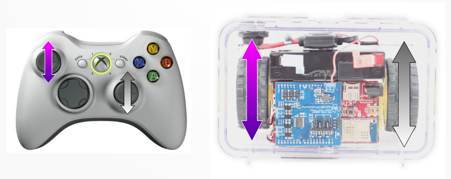
Tank drive is a direct-drive control where one joystick is used for each side of the drive train. The left joystick moves the left motor forward and backward, and the right joystick moves the right motor forward and backward. To turn, you move one joystick forward and the other in reverse. This control scheme offers the driver complete control, but tends to have a steeper learning curve.
But, this scheme is the easiest to implement in software because of its simplicity!
If you have some experience programming, try implementing this drive control now. Otherwise, read on for step-by-step instructions.
C++
Create a Drive Subsystem
In our code, we use subsystems to organize our code by component. Since we need to control our drive base, we will start by creating a drive subsystem that controls the two drive motors.
- In the Explorer sidebar in VSCode (Ctrl + Shift + E), right click on the
C++/src/main/cpp/subsystemsfolder and select “Create a new class/command”.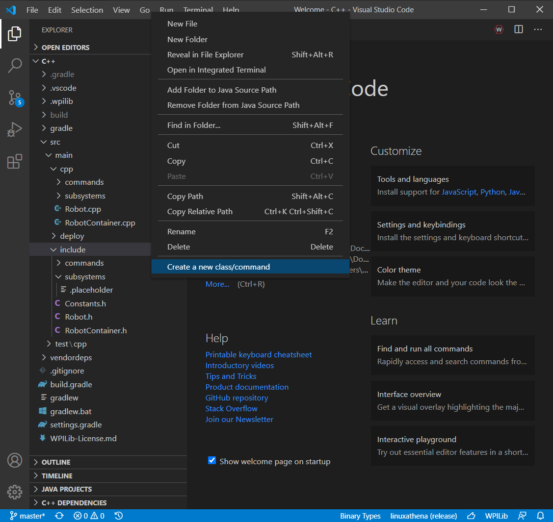
- In the prompt bar, choose “Subsystem (New)” then type the name for your new subsystem. “DriveSubsystem” will be used in these instructions.
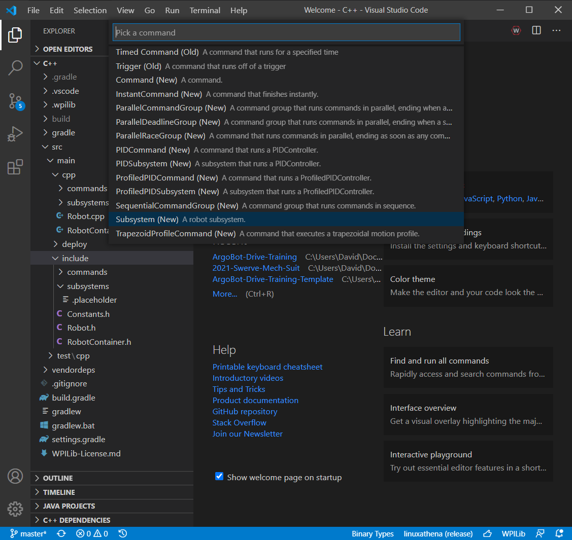
- You should see two new files:
src/main/cpp/subsystems/DriveSubsystem.cppandsrc/main/include/subsystems/DriveSubsystem.h. Click onDriveSubsystem.hto open it.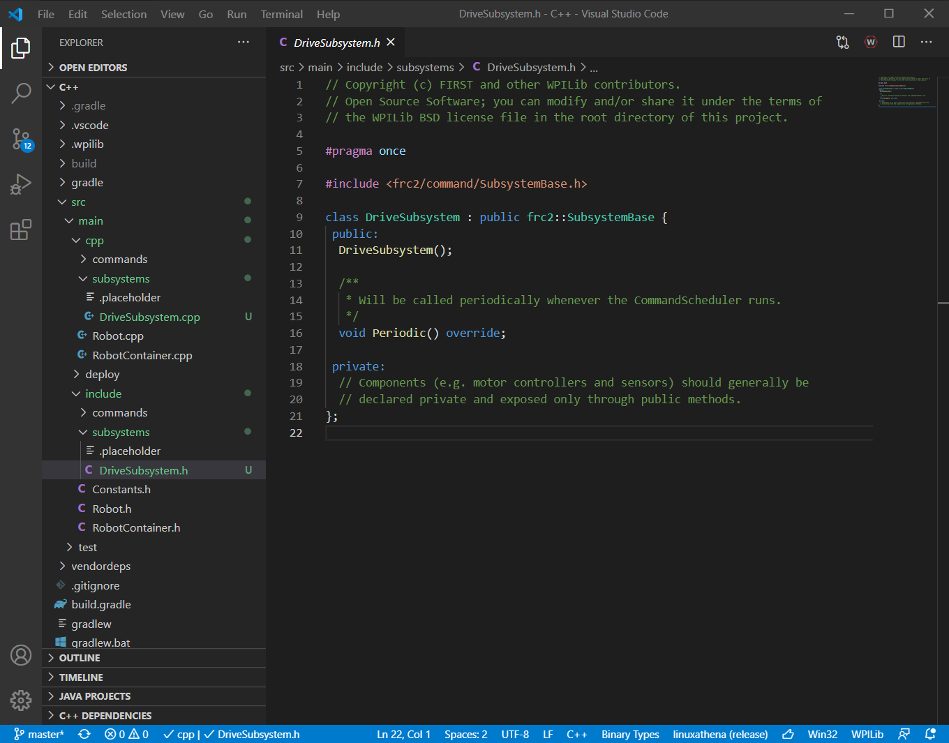
Add Motors to Drive Subsystem
- With the
DriveSubsystem.hfile open, we need to start with including the file that describes the motor controllers. This is known as a “header file” and ends in the.hextension. To do this, add a new line below the existing#includeline and add#include <ctre/Phoenix.h> - Next we need to add two motors. We’ll add them in the
privatesection of the subsystem declaration. Add the motors like this:private: // Components (e.g. motor controllers and sensors) should generally be // declared private and exposed only through public methods. TalonSRX m_leftMotor; TalonSRX m_rightMotor; - The final change in the subsystem header file is we need to modify the constructor so we can set the IDs for each motor. The existing constructor is the function that has the same name as our subsystem, so
DriveSubsystem();. To add two ids for our two motors, we will add parameters so the declaration now looks like this:public: DriveSubsystem(const int leftDriveID, const int rightDriveID); - At this point,
DriveSubsystem.hshould look like this:DriveSubsystem.h
// Copyright (c) FIRST and other WPILib contributors. // Open Source Software; you can modify and/or share it under the terms of // the WPILib BSD license file in the root directory of this project. #pragma once #include <frc2/command/SubsystemBase.h> #include <ctre/Phoenix.h> class DriveSubsystem : public frc2::SubsystemBase { public: DriveSubsystem(const int leftDriveID, const int rightDriveID); /** * Will be called periodically whenever the CommandScheduler runs. */ void Periodic() override; private: // Components (e.g. motor controllers and sensors) should generally be // declared private and exposed only through public methods. TalonSRX m_leftMotor; TalonSRX m_rightMotor; }; - Now we want to make corresponding changes to the subsystem source file, which is named
DriveSubsystem.cpp. This file will have the implementation of the functions we’ve declared in the header. An easy way to switch to this file is Alt + O or you can find the file in the explorer sidebar.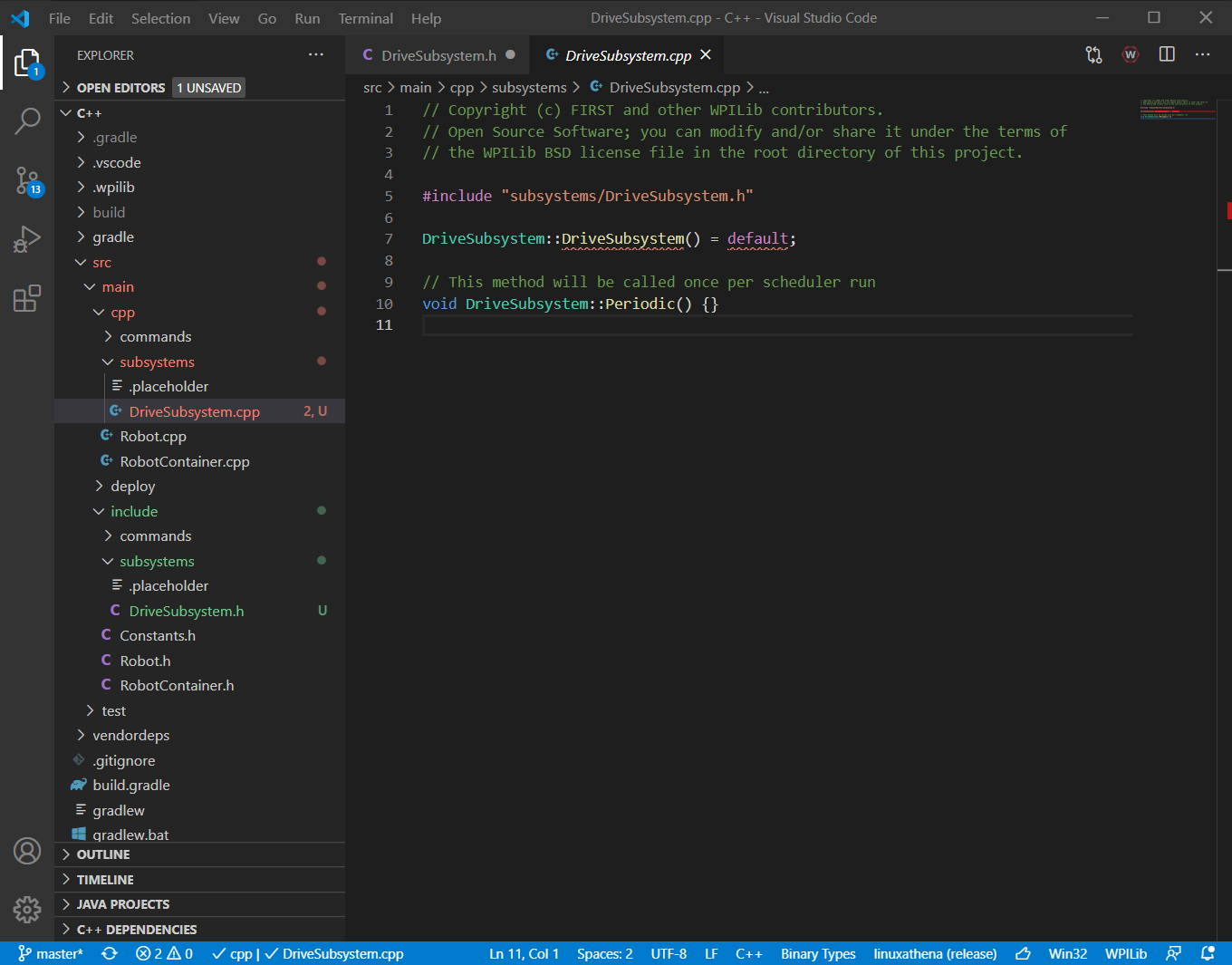
- You’ll notice some red squiggly lines under the constructor definition. This is because we modified this in the header file, and now the two files don’t match. Let’s fix that now! We want to add the new parameters and initialize our two motors. Do this by changing the constructor to this:
DriveSubsystem::DriveSubsystem(const int leftDriveID, const int rightDriveID) : m_leftMotor(leftDriveID) , m_rightMotor(rightDriveID) { } - Now we’ve added the motors to our subsystem! Your
DriveSubsystem.cppfile should look like this:DriveSubsystem.cpp
// Copyright (c) FIRST and other WPILib contributors.
// Open Source Software; you can modify and/or share it under the terms of
// the WPILib BSD license file in the root directory of this project.

#include "subsystems/DriveSubsystem.h"

DriveSubsystem::DriveSubsystem(const int leftDriveID, const int rightDriveID)
  : m_leftMotor(leftDriveID)
  , m_rightMotor(rightDriveID) {

}

// This method will be called once per scheduler run
void DriveSubsystem::Periodic() {}
Add Controller And Subsystem To Robot
Now we’ve got a drive subsystem, but we don’t have a way of controlling it. Because we use the controller to control many subsystems on the robot, we need to add it to RobotContainer instead of a subsystem.
- Start by opening
RobotContainer.h. A shortcut is to press Ctrl + P and type the name of the file. - In
RobotContainer.h, we’ll start by including the header files we need. First, we want to include our subsystem fromsubsystems/DriveSubsystem.hand then we’ll include the XBox Controller library fromfrc/XboxController.h. The include statements should look like this:#include "subsystems/DriveSubsystem.h" #include <frc/XboxController.h> - Now we’ll add a controller and a drive subsystem by adding an instance of each class to the
privatesection of theRobotContainerdeclaration.private: // The robot's subsystems and commands are defined here... DriveSubsystem m_drive; frc::XboxController m_controller; - After this,
RobotContainer.hshould look like this:RobotContainer.h
// Copyright (c) FIRST and other WPILib contributors. // Open Source Software; you can modify and/or share it under the terms of // the WPILib BSD license file in the root directory of this project. #pragma once #include <frc2/command/Command.h> #include "subsystems/DriveSubsystem.h" #include <frc/XboxController.h> /** * This class is where the bulk of the robot should be declared. Since * Command-based is a "declarative" paradigm, very little robot logic should * actually be handled in the {@link Robot} periodic methods (other than the * scheduler calls). Instead, the structure of the robot (including subsystems, * commands, and button mappings) should be declared here. */ class RobotContainer { public: RobotContainer(); frc2::Command* GetAutonomousCommand(); private: // The robot's subsystems and commands are defined here... DriveSubsystem m_drive; frc::XboxController m_controller; void ConfigureButtonBindings(); }; - Next, we’ll switch to
RobotContainer.cppto add our implementation. - The first step is to add our controller and drive subsystem initialization to the constructor. Our controller will be in port 0, left drive will be ID 2, and right drive will be ID 1. Add these initializations to the connector:
RobotContainer::RobotContainer() : m_drive{2, 1} , m_controller{0} { // Initialize all of your commands and subsystems here ... - And now we have a controller and drive subsystem added to our robot! Unfortunately, it doesn’t drive yet, but we’ll do that next.
RobotContainer.cppshould look like this at this point:RobotContainer.cpp
// Copyright (c) FIRST and other WPILib contributors.
// Open Source Software; you can modify and/or share it under the terms of
// the WPILib BSD license file in the root directory of this project.

#include "RobotContainer.h"

RobotContainer::RobotContainer()
  : m_drive{2, 1}
  , m_controller{0} {
  // Initialize all of your commands and subsystems here

  // Configure the button bindings
  ConfigureButtonBindings();
}

void RobotContainer::ConfigureButtonBindings() {
  // Configure your button bindings here
}

frc2::Command* RobotContainer::GetAutonomousCommand() {
  // An example command will be run in autonomous
  return nullptr;
}
Add Motor Control Logic
- Now we need to go back to
DriveSubsystem.h - Create a new function declaration for our tank drive. This function needs one input for each joystick input (left and right) and will only output to the motors themselves. This function will go in the
publicsection after the constructor.void TankDrive(const double leftDrive, const double rightDrive); DriveSubsystem.hshould look like this:DriveSubsystem.h
// Copyright (c) FIRST and other WPILib contributors. // Open Source Software; you can modify and/or share it under the terms of // the WPILib BSD license file in the root directory of this project. #pragma once #include <frc2/command/SubsystemBase.h> #include <ctre/Phoenix.h> class DriveSubsystem : public frc2::SubsystemBase { public: DriveSubsystem(const int leftDriveID, const int rightDriveID); void TankDrive(const double leftDrive, const double rightDrive); /** * Will be called periodically whenever the CommandScheduler runs. */ void Periodic() override; private: // Components (e.g. motor controllers and sensors) should generally be // declared private and exposed only through public methods. TalonSRX m_leftMotor; TalonSRX m_rightMotor; };- Now switch to
DriveSubsystem.cppand we’ll add the definition forDriveSubsystem::TankDrive(). - We need to output to each motor, so we’ll use the
::Setmethod inControlMode::PercentOutputmode. Make a function body that looks like this:void DriveSubsystem::TankDrive(const double leftDrive, const double rightDrive) { m_leftMotor.Set(ControlMode::PercentOutput, leftDrive); m_rightMotor.Set(ControlMode::PercentOutput, rightDrive); } - The full
DriveSubsystem.cppshould now look like this:DriveSubsystem.cpp
// Copyright (c) FIRST and other WPILib contributors. // Open Source Software; you can modify and/or share it under the terms of // the WPILib BSD license file in the root directory of this project. #include "subsystems/DriveSubsystem.h" DriveSubsystem::DriveSubsystem(const int leftDriveID, const int rightDriveID) : m_leftMotor(leftDriveID) , m_rightMotor(rightDriveID) { } void DriveSubsystem::TankDrive(const double leftDrive, const double rightDrive) { m_leftMotor.Set(ControlMode::PercentOutput, leftDrive); m_rightMotor.Set(ControlMode::PercentOutput, rightDrive); } // This method will be called once per scheduler run void DriveSubsystem::Periodic() {} - Finally, let’s connect the controller joysticks to our new
TankDrive()function. Start by openingRobotContainer.cpp - First, we need to add another header to support running commands. Include
frc2/command/RunCommand.h#include <frc2/command/RunCommand.h> - In the constructor body, we’re going to set a default command for our drive subsystem. We want the left y joystick axis to control the left motor and the right y joystick axis to control the right motor. This may be a bit complicated looking, but try copying it now and see if you can find the parts that do each of these steps.
m_drive.SetDefaultCommand(frc2::RunCommand( [this] { m_drive.TankDrive(m_controller.GetRawAxis(static_cast<int>(frc::XboxController::Axis::kLeftY)), m_controller.GetRawAxis(static_cast<int>(frc::XboxController::Axis::kRightY))); }, {&m_drive})); - Now
RobotContainer.cppshould look like this:
RobotContainer.cpp
// Copyright (c) FIRST and other WPILib contributors.
// Open Source Software; you can modify and/or share it under the terms of
// the WPILib BSD license file in the root directory of this project.

#include "RobotContainer.h"
#include <frc2/command/RunCommand.h>

RobotContainer::RobotContainer()
  : m_drive{2, 1}
  , m_controller{0} {
  // Initialize all of your commands and subsystems here

  m_drive.SetDefaultCommand(frc2::RunCommand(
    [this] {
      m_drive.TankDrive(m_controller.GetRawAxis(static_cast<int>(frc::XboxController::Axis::kLeftY)),
                        m_controller.GetRawAxis(static_cast<int>(frc::XboxController::Axis::kRightY)));
    },
    {&m_drive}));

  // Configure the button bindings
  ConfigureButtonBindings();
}

void RobotContainer::ConfigureButtonBindings() {
  // Configure your button bindings here
}

frc2::Command* RobotContainer::GetAutonomousCommand() {
  // An example command will be run in autonomous
  return nullptr;
}
Excellent! Now we’re ready to test out the code!
Try It Out
- Connect to the WiFi for the robot.
- Open the FRC Driver Station. You should see green communication with the robot

- Back in VSCode, press Ctrl + Shift + P to get your command pallette and select
WPILib: Deploy Robot Code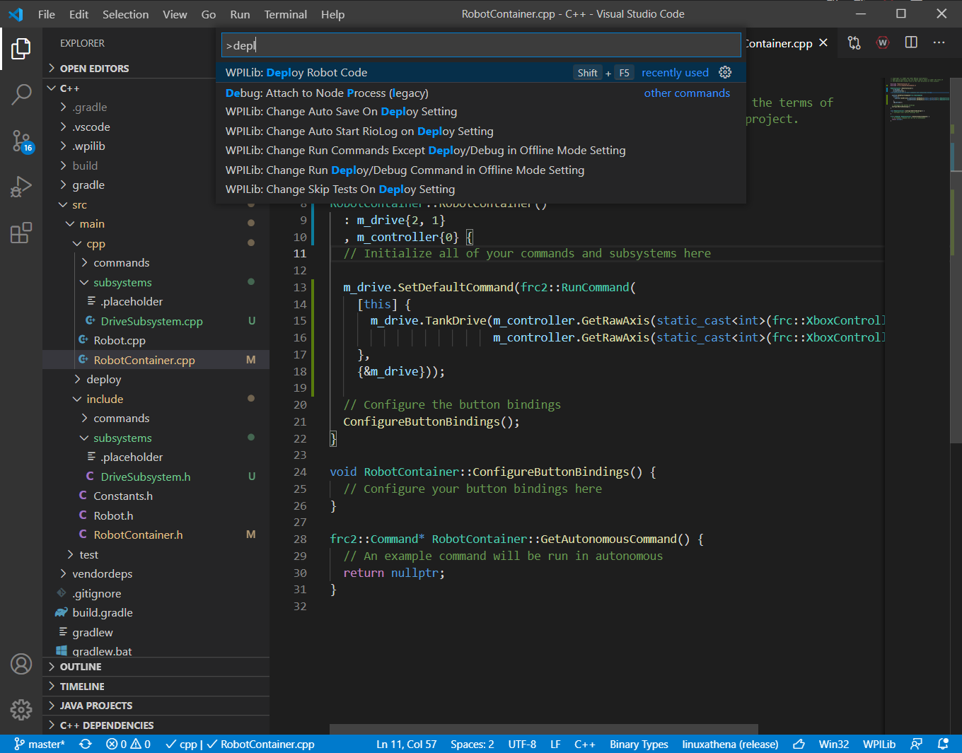
- Return to the driver station. Make sure your controller is plugged in, stand clear of the robot, and enable the robot.
- Try driving the robot. Make sure to disable whenever you are not holding the controller.
- Does it work?
- Is there anything that doesn’t do what you were expecting?
Fixing a Bug
- You may have noticed the motors aren’t moving as you expected! The right motor goes backward when you command it forward and the left motor goes forward when you command it forward. There are a couple issues here. First, you’ll notice that the motors are flipped 180 degrees relative to one another, so forward will make one motor go forward and reverse the other. The other issue is less obvious.
- Open the USB menu of the driver station (with the robot disabled) and select your controller. When you move the joysticks forward and backward, you should see axis values change in the little display.

- Notice how “forward” leads to negative values? We can fix it! We’ll just need to make a couple tweaks.
- First, we will invert the left motor in
DriveSubsystem.cpp. In the body of the constructor, we will call theSetInverted()method ofm_leftMotor:DriveSubsystem::DriveSubsystem(const int leftDriveID, const int rightDriveID) : m_leftMotor(leftDriveID) , m_rightMotor(rightDriveID) { m_leftMotor.SetInverted(true); } - Now, we need to invert our joystick y axes in
RobotController.cpp. To do this, we will multiply our joystick values by-1.m_drive.SetDefaultCommand(frc2::RunCommand( [this] { m_drive.TankDrive(m_controller.GetRawAxis(static_cast<int>(frc::XboxController::Axis::kLeftY)) * -1, m_controller.GetRawAxis(static_cast<int>(frc::XboxController::Axis::kRightY)) * -1); }, {&m_drive})); - Now, try testing your fixes by deploying your code and running the robot in the driver station.
LabVIEW
Open the Tank Drive Template VI
ArgoBot V1
- Open
ArgoBotDriveTraining.lvprojfrom thesrc/ArgobotV1folder of the training repository. This will bring up the project explorer window. - From the project explorer window, open
Drive_Tank.vi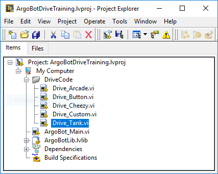
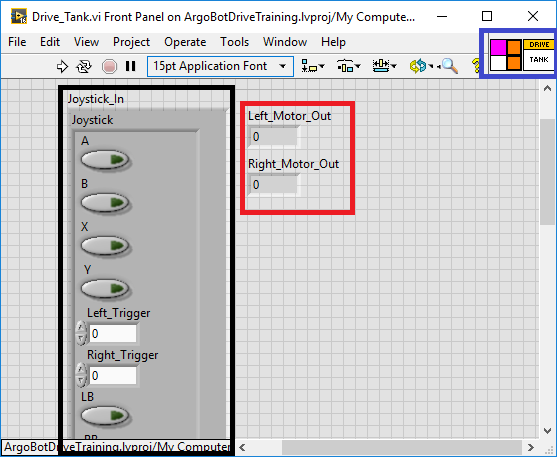
- You will first encounter the front panel. On the front panel, you can see a bundle of joystick inputs (Black), numeric motor outputs (Red), and the VI icon and input/output terminals (Blue).
- Go to the block diagram by pressing Ctrl + E or by clicking “Window”>”Show Block Diagram”
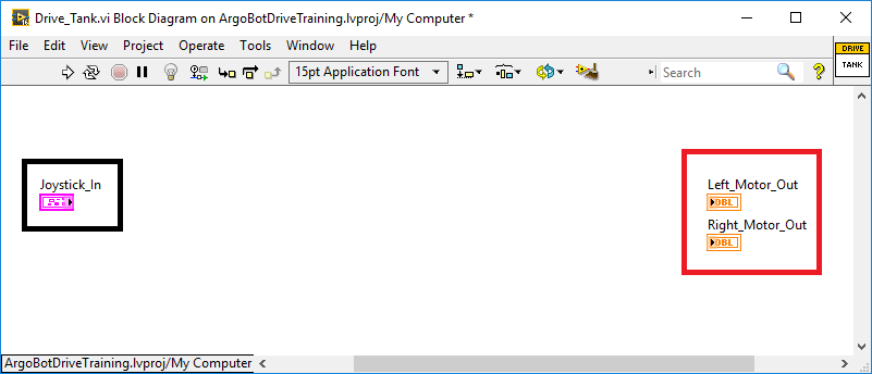
- On the block diagram, you’ll see a control (input) with the joystick bundle (Black) and indicators (outputs) for the motors (Red).
ArgoBot V2
- Open
ArgoBotV2.lvprojfrom thesrc/ArgobotV2folder of the training repository. This will bring up the project explorer window. - From the project explorer window, open
Drive_Tank.vi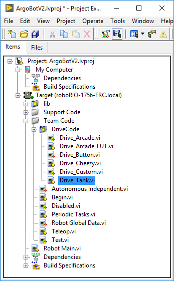
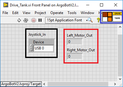
- You will first encounter the front panel. On the front panel, you can see a joystick input devref (Black), numeric motor outputs (Red), and the VI icon and input/output terminals (Blue).
- Go to the block diagram by pressing Ctrl + E or by clicking “Window”>”Show Block Diagram”
- On the block diagram, you’ll see a control (input) with the joystick input devref (Black), some code to process the joystick input (Blue), and indicators (outputs) for the motors (Red).

Extract the Joystick Values
ArgoBot V1
- In the block diagram, right click on the white space to bring up the tools palette.
- Most of the tools we need are in the “Programming” palette at the top
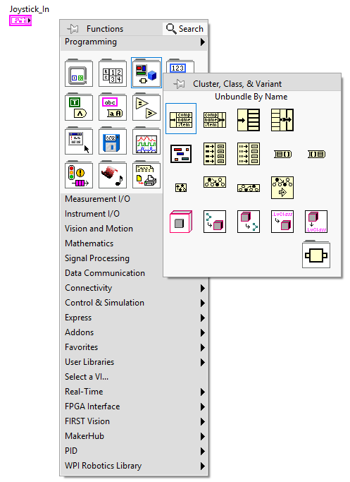
- Open the “Cluster, Class, & Variant” section and select “Unbundle By Name”
- Place the new block on the right side of the Joystick_In block
- Connect the output of Joystick_In to the input of the unbundle block with a wire. Do this by clicking the dot on one block then clicking the dot on the other.

- Drag the little blue dot on the bottom of the unbundle block down to make the block two cells high.
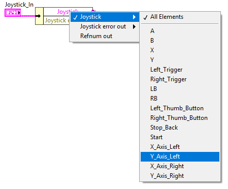
- Select “Joystick”>”Y_Axis_Left” and “Joystick”>”Y_Axis_Right” by left clicking on each of the two cells when you get the “finger” cursor.
ArgoBot V2
- In the block diagram, right click on the white space to bring up the tools palette.
- Most of the tools we need are in the “Programming” palette at the top
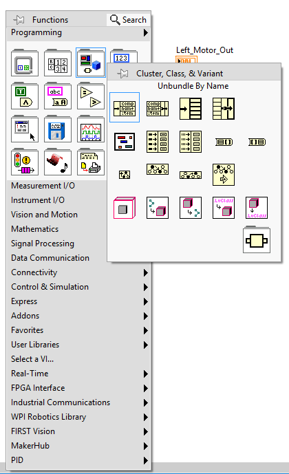
- Open the “Cluster, Class, & Variant” section and select “Unbundle By Name”
- Place the new block on the right side of the Joystick_In block
- Connect the “Named Axes” output of Joystick Name to the input of the unbundle block with a wire. Do this by clicking the dot on one block then clicking the dot on the other.

- Drag the little blue dot on the bottom of the unbundle block down to make the block two cells high.
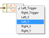
- Select “Left_Y” and “Right_Y” by left clicking on each of the two cells when you get the “finger” cursor.
Connect the Joystick Inputs to the Motor Outputs
ArgoBot V1
- Wire the “Y_Axis_Left” input to the “Left_Motor_Out” output
- Wire the “Y_Axis_Right” input to the “Right_Motor_Out” output

- Make sure you save your changes by pressing Ctrl + S or clicking “File”>”Save”
ArgoBot V2
- Wire the “Left_Y” input to the “Left_Motor_Out” output
- Wire the “Right_Y” input to the “Right_Motor_Out” output

- Make sure you save your changes by pressing Ctrl + S or clicking “File”>”Save”
Try It Out
ArgoBot V1
- Open the project explorer window
- Open
ArgoBot_Main.vi - Navigate to the block diagram
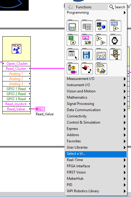
- In the tools palette, choose “Select a VI…”
- Wire the
Read_Joystickbundle to theJoystick_Ininput - Wire the
Left_Motor_Outoutput to theLeft Motorbundle element - Wire the
Right_Motor_Outoutput to theRight Motorbundle element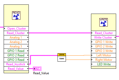
- Go back to the front panel
- Save the VI
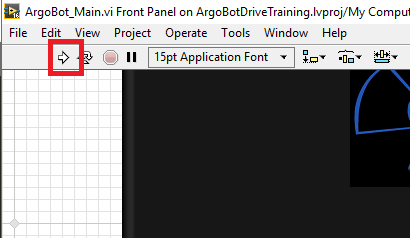
- Connect the ArgoBot and click the “Run” arrow
- Try driving the tank drive.
- Does it work?
- Is there anything that doesn’t do what you were expecting?
ArgoBot V2
- Open the project explorer window
- Open
Teleop.vi - Navigate to the block diagram
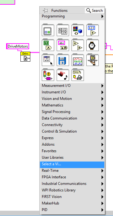
- In the tools palette, choose “Select a VI…”
- Wire the
JoystickDevRefoutput of Joystick RefNum Registry Get to theJoystick_Ininput - Wire the
Left_Motor_Outoutput to theLeftSpeedinput of RobotDriveMotors - Wire the
Right_Motor_Outoutput to theRightSpeedinput of RobotDriveMotors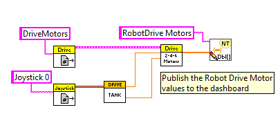
- Save the VI
- Go back to the project explorer and open
Robot Main.vi - Connect the ArgoBot and click the “Run” arrow. This will load your code onto the robot.
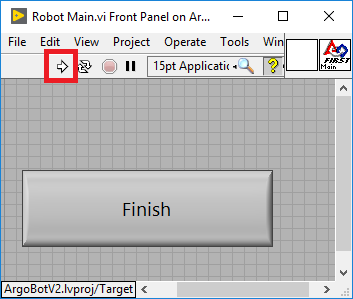
- Open the FRC Driver Station program and click “Enable” to run the robot

- Try driving the tank drive.
- Does it work?
- Is there anything that doesn’t do what you were expecting?
Fixing a Bug
- You may have noticed the left motor is going backwards! This is because the two motors are flipped 180 degrees, so forward will make one motor go forward, and reverse the other.
- We can fix it! All we need to do is make the value opposite on the left motor.
- First, open
Drive_Tank.viagain and go to the block diagram. - Right click on the left motor’s orange wire and select “Insert”>”Numeric Palette”>”Negate”
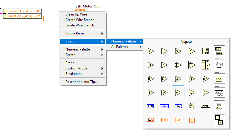
- This will insert a new negate block, which multiplies the input by -1, in line with the wire.

- Save again
- Try running again from
ArgoBot_Main.vi
Congratulations! You have a driving robot! Try driving it a little to see what you do or don’t like. You’ll want to improve on the design in future exercises.
Another Fix Using ArgoBot v2
If you are using and ArgoBot v2, there’s a better way of fixing a motor that turns the wrong direction! Every motor has an “Invert” property that is designed to allow a programmer to make the “forward” direction of a motor reverse of the default forward direction.
Before you try this new method, remove the fix from before then do the following:
- Open
Begin.vifrom the project explorer - Switch to the block diagram
- Change the
Left Motor 1 Invinput constant to true by clicking on the green F block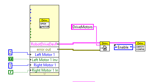
- Save and try running your code
Keep in mind that future exercises will use the v1 fix instead of the v2 fix, but competition robot code will set motor direction in Begin.vi.
Congratulations! You have a driving robot! Try driving it a little to see what you do or don’t like. You’ll want to improve on the design in future exercises.
Next you’ll be trying a new drive type: arcade drive.
| <-Previous | Index | Next-> |