ArgoBot Drive Training
Here you'll find some tutorials to write drive code for the ArgoBot (or any robot) using LabVIEW or C++
This project is maintained by FRC1756-Argos
Tutorial 3: Button Drive
Seems like you’ve mastered driving with joysticks. What about all those buttons on the controller? Now, we’ll try a different approach to driving: button drive. This exercise will skip over some of the more detailed steps covered in the tank drive and arcade drive tutorials, so you may want to refer to those tutorials if you get stuck.
What is “Button Drive”?
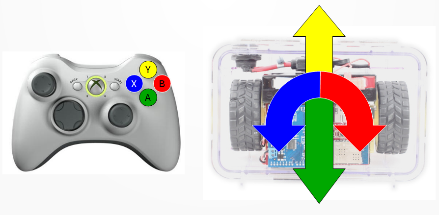
Button drive may be the strangest drive control covered in this training because it uses pure digital controls. Typically we use analog controls like joysticks because they allow both slow and fast driving, but with digital controls like buttons we get “stop” and “go” with no speed control. We will use the four right hand buttons to go forward, backward, turn left, and turn right as shown in the diagram. To do this, we will use the tank and arcade drive concepts and add in digital controls.
If you have already used LabVIEW, try implementing this drive control now. Otherwise, read on for step-by-step instructions.
Control Design
To make a working button drive, we need to implement the following:
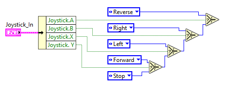
if A is pressed:
  Reverse
else if B is pressed:
  Right
else if X is pressed:
  Left
else if Y is pressed:
  Forward
else:
  Stop
And the motor outputs for each state should be as follows:
| Mode | Left Output | Right Output |
|---|---|---|
| Forward | 1 | 1 |
| Reverse | -1 | -1 |
| Left | 1 | -1 |
| Right | -1 | 1 |
| Stop | 0 | 0 |
Note that the left motor must be inverted as in the previous drives because forward is inverted on the left motor. The order of the button checks is not important, but what is important is that we can only ever drive one way at a time in button drive. There will be no forward and turn a little this time :)
If you have any ideas on how to do this, try it on your own before following the step-by-step instructions.
C++
Create a New Drive Function
- Let’s start in
DriveSubsystem.h - We’ll make a new function declaration here for button drive. This time we have four button value inputs and these will be boolean values instead of doubles because buttons only have on or off values.
void ButtonDrive(const bool forward, const bool right, const bool reverse, const bool left);Note that the parameter names are based on the function of each input instead of the button we plan on using.
- Now, we’ll add the definition of the function we’ve created in
DriveSubsystem.cppvoid DriveSubsystem::ButtonDrive(const bool forward, const bool right, const bool reverse, const bool left) { }Notice how we can align parameters so lines aren’t so long. C++ lets you format your code with whitespace without changing how your programs work.
- Because we want to only drive based on one button input at a time, we’ll use a combination of
if,else if, andelseblocks.ifchecks a condition (kind of like asking a question where the answer is ‘yes’ or ‘no’) and runs a block if that condition is true.else ifmust always follow aniforelse ifstatement. This checks another condition likeif, but only runs a block if the previous conditions were false and the new condition is true.elsemust always follow aniforelse ifstatement and will also be the last statement in a condition. Its block will be executed if none of the previous conditions were true.
- In this case, let’s prioritize forward and reverse motion over turning. That way if you press both the forward button and turn button, the robot will drive forward. To do this, we’ll put the highest priority commands earlier in the case structure.
if(forward) { } else if(reverse) { } else if(right) { } else if(left) { } else { } - Now we need to control the motors in each case. We could control the motors directly like in arcade and tank drive, but we can also reuse an existing drive function in our subsystem. This makes it easier to make changes later.
if(forward) { ArcadeDrive(0.5, 0); } else if(reverse) { ArcadeDrive(-0.5, 0); } else if(right) { ArcadeDrive(0, 0.5); } else if(left) { ArcadeDrive(0, -0.5); } else { ArcadeDrive(0, 0); } - Finally, let’s add our new drive function to
RobotContainerand connect buttons to the function parameters. - Open
RobotContainer.cppand replace your existing drive function withButtonDrivein theSetDefaultCommandcall.m_drive.ButtonDrive(/* Y button */, /* B button */, /* A button */, /* X button */);Note that the
/* */parts are comments, so they aren’t run by the robot program. - Just like axes, there’s an
frc::XboxController::Buttonenum so we can use button names and there’s aGetRawButtonto detect if the button is pressed.m_drive.ButtonDrive(m_controller.GetRawButton(static_cast<int>(frc::XboxController::Button::kY)), m_controller.GetRawButton(static_cast<int>(frc::XboxController::Button::kB)), m_controller.GetRawButton(static_cast<int>(frc::XboxController::Button::kA)), m_controller.GetRawButton(static_cast<int>(frc::XboxController::Button::kX)));
Try It Out
- Deploy your code.
- Enable the robot in the Driver Station.
- Be very careful because the robot may move quickly when you press a button
LabVIEW
Open and Unbundle Joysticks
Just like before, we’ll start by opening the drive VI and unbundling the joystick values we want.
- Open
Drive_Button.vifrom the project explorer - Go to the block diagram
- Using the tool palette, insert an “Unbundle By Name” block
- Connect the unbundle block to the
Joystick_Incontrol - Expand the unbundle to 4 cells
- Select
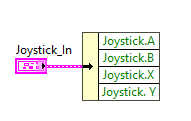
Joystick.A,Joystick.B,Joystick.X, andJoystick.Y,
When you are complete, you should end up with the following:
Implement the Design
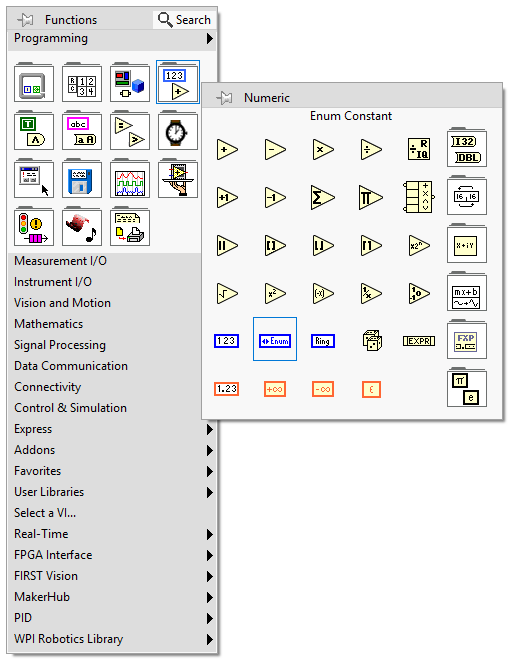
- First, we’ll create an ‘enum’ constant for the drive mode. An enum is a data type that lets us name a set of states (e.g. ‘Forward’, ‘Reverse’, etc.) so we can pass the state information around. Probably best to see it in action!
- Now we need to add some states to the enum. Right click on it and select ‘Edit Items…’
- Insert all the drive states. Your order may be different than mine, that is OK! Just make sure there are only states numbered 0-4.
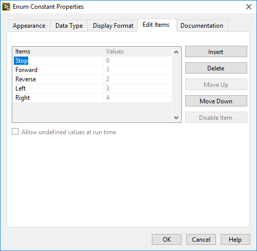
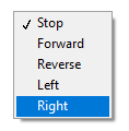
- Now when you left click on the enum constant, you can see the states you created
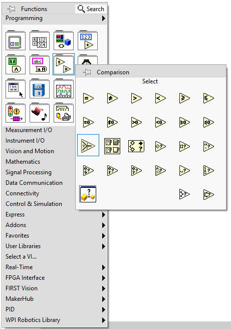
- To use these states, we need some selectors! Selectors take a boolean selection input and choose between two inputs to wire to the output.
Essentially, if we wire a button to the selector, when the button is pressed, the ‘T’ input comes out, and when the button is released the ‘F’ input comes out.
Place a selector from the comparisons palette
- Now, let’s make a cascading bridge of selectors. This implements the if, else if logic described before.
The input at the top of the bridge has top priority, so in the figure below, when
Joystick.Ais pressed it doesn’t matter what other buttons are pressed. A’s output will always be asserted. Inputs above other inputs will have priority over those below. The bottommost value is called ‘default’ because it is only output if no button is pressed.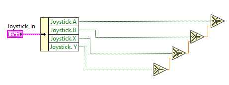
- Notice, the wires are all orange, but the enum is blue. This is because none of the wires are connected yet.
Make some copies of your enum constant and wire one to all the
Trueinputs and one to the default input. - Change the constant values to match the logic described in our control design above.
- Now we’re going to use our first structure: the case structure. Structures are boxes that perform special operations on the blocks inside.
The case structure takes a condition input (in our case the drive mode) and swaps out the contents based on mode.
First, select “Case Structure” from the “Structures” palette and draw a box between the selector cascade and the outputs.
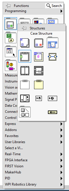
- Wire the output of the selector cascade to the case structure’s question mark input (the green box) and wire the two motor outputs to the right wall of the case structure.
Notice that the outputs have broken wires because no inputs are connected yet. We’ll fix that soon

- Right click on the drop down menu of the case structure and click “Add Case For Every Value”. This will make one case for every enum value we made earlier.
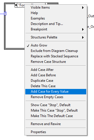
- Finally, add some “DBL Numeric Constant” values from the numeric palette to connect inside each case. Use the table above to choose the right values.

- Save your VI
Try It Out
Now that we’ve got a new drive control VI, let’s try driving with it.
- Open
ArgoBot_Main.vi - Go to the block diagram
- Right click on the
Drive_Arcadeblock and select “Replace”>”All Palettes”>”Select A VI…” - Select
Drive_Button.vi - Save and run the VI
Try driving it a little to see what you do or don’t like. You’ll want to improve on the design in future exercises.
What did you like more or less about this drive style? Is there anything that makes it hard to drive?
Congratulations! Now you have three different drive styles under your belt! Next up: Cheezy drive!
| <-Previous | Index | Next-> |